K9DP BCI Filter - INSIDE THE G90!
Executive Summary
Oh yeah. This is the ticket.
The $20 K9DP QRP broadcast band filter. Nice price to performance ratio, easy to assemble, and small.
If you have a G90 and live 1.5 miles from a 50 KW AM station, you know why you need one. If you travel with your G90, you may learn why you need one.
Turns out, this filter can be easily installed INSIDE the G90, in the form of a new receive jumper. This permits filtering to be done in the receive path only.
No external boxes and cables, and better yet, NOT transmitting through the filter, which happens if you put the filter after the antenna tuner outside the box.
In my radio, the install looks like this. The filter is visible as the heat shrink-encased mass on the right top side of the speaker hole, under the top circuit board.
IMPORTANT NOTE 6/1/2025: I've been told the latest model G90s have an additional partition between the two main boards (seen on a Power Pole version) that may complicate installation, please check your radio before proceeding. SPM

What's a K9DP QRP BCB Filter?

If you're fond of inexpensive or home-constructed QRP rigs, you know many need help rejecting strong broadcast band signals. This kit is an affordable and effective tool for that.
What's the Filter Do?
Like most BCB filters for QRP use, this filter is designed to have massive attenuation in the broadcast band, and virtually none above 3.5 mHz.
As some of us know, this otherwise great value radio sometimes needs help when operating in adverse RF environments. Like my QTH, 1.5 crow miles from WMVP, a 50 kilowatt AM station.

The spectrum analyzer pic of my build shows:
1) about 70 dB of attenuation at AM at WMVP's frequency (1 MHz);
2) about 30 dB of attenuation at 1.8 MHz - not great if you're a big 160 meter fan, but for me, not an issue for a portable rig.
NB: A BCB filter that is effective with no loss at 160 is not quick, easy or small, and would probably need to be homebrewed from scratch. Can't let excellence be the enemy of good enough; because
3) the 50 dB of attenuation above 3.5 MHz is just the ticket for my use case.
Why Did I Wait So Long to Do This?
Because the G90 warranty hadn't expired.
The last straw was misplacing my homebrew filter after my fall trip to TF😒
But last month my 18 month warranty period ended. This means no down side to getting inside the radio to do the MARS mod, and a chance to scope out installing a broadcast band filter inside the box.
The Build
Read about it and watch the videos linked on K9DP's web page. About the only thing to be aware of is that we won't be using the onboard BNC connectors offered, but will use IPX jumpers compatible with the G90 boards.
You probably won't have test leads compatible with those pesky IPX jumpers, and you'll want to test the filter before taking the time to put it in the radio. I elected to solder temporary wire jumpers on the board that would accept my 0.1 inch test headers (see pic below). Or you might solder the provided BNCs to the board and remove them post-test.
I say you should test because it's the right thing to say, but we both know this kit is so simple the odds of a build fail are really small. I say check anyway, because it is a bit of work getting the filter installed in the radio. YMMV.

Where to Put the filter?
YO3HJV's excellent G90 blog provided the G90 Repair Manual with block diagrams offering good insight into where the filter might be placed inside the radio. See https://YO3HJV.blogspot.com for those diagrams and a wealth of other G90 info.
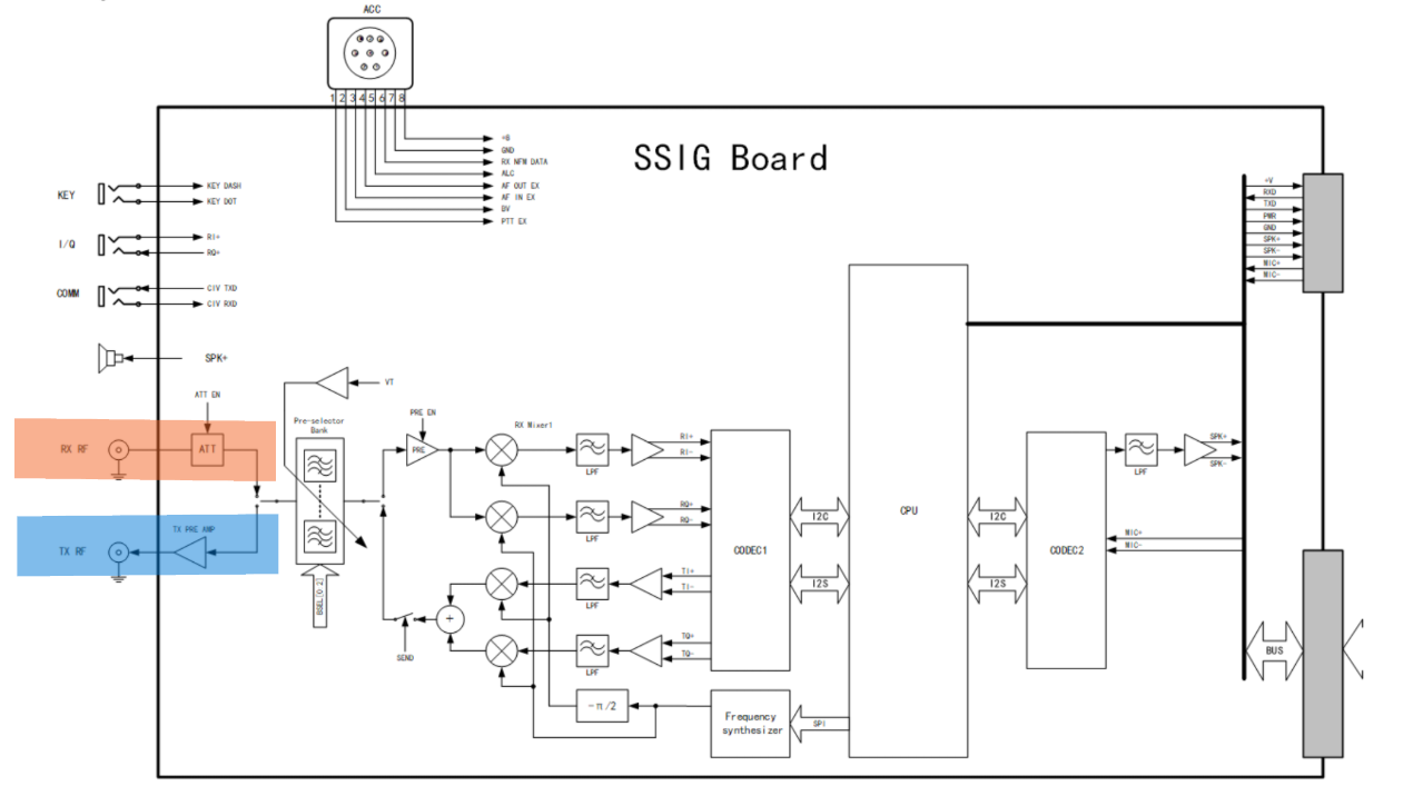
You probably already know most of the RF signal work in the G90 happens on two boards. They are the Small Signal Board (SSI Board) and the BASE Board. The SSIG Board is at the top of the radio, and the BASE Boaard at the...well, base. Who knew?
The BASE Board flowchart from the repair manual shows how signals get into the radio from the antenna jack and eventually to the SSIG board.
Follow the receive path highlighted in orange from right to left below. The switch between receive and transmit path occurs at the orange/blue intersection, with the transmit path shown in blue, just FYI.
Signal arrives at the antenna, passes through the antenna tuner and leaves the BASE board at the jack marked RX at the top left.

A grey jumper in the G90 transfers RX signal between the two boards. The cable runs between connectors marked RX on each board.
The SSIG Board flowchart orange path shows that the signal from the BASE board enters the SSIG board from the left, with signals passing (optionally) through the attenuator, and on to the bandpass filters before signal processing begins.
Step by Step
You can find links to a few build videos on K9DP's site, so we'll focus on how to get the filter inside the radio.
The K9DP kit order page allows you to order the kit with male or female BNC connectors. You could build the filter this way, but it would be a bit unwieldy to install inside the radio using BNC-sized hardware.
The sensible solution for me was to buy a new longer IPX jumper, cut it in half, and solder the leads to the BNC connection points on the K9DP board.
These are the jumpers I bought.

The RG178 was good quality and easy to prepare and solder to the board. This same connector goes by other names depending on the manufacturer - just an FYI if you start losing your mind trying to determine if a cable has the correct connector - these worked well.
If you haven't seen what's going on with that tiny connector, here's a close up that may make it easier to understand why mating the cable to the board can be a bit annoying......and require care when mating.

A prepared jumper looks like this. Pretty exciting, huh?

The jumper lengths should be what works for your install. You can estimate my lengths from the pics that follow. Because yep, I forgot to write lengths down.
I soldered the jumpers to the K9DP board as shown below. Also visible in this pic is a piece of large diameter heat shrink tubing, provided with the kit, and just right for insulating the filter from the G90 innards. I didn't shrink the tubing until the filter tested ok in the radio. Again, YMMV.

Getting into the G90 is straightforward. Remove the head, remove the six screws from the top panel, remove the four screws that hold the SSIG board in and you're ready to begin.


This pic shows the filter installed. The SSIG Board has been returned to its original orientation, with the filter between the two boards and just visible on the right side of the speaker hole. The new RX jumper has been reinstalled in its socket at the upper left side of the pic.


Comments